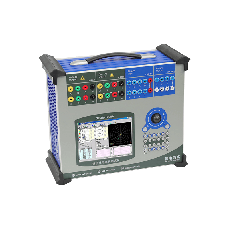
Relay protection devices, as key safety protection components in power systems, directly affect the safety and stability of power grid operation with their performance. Action time, as an important indicator to measure the response speed of relay protection devices, reflects the duration from the input of fault signals to the output of actions of the protection devices. Accurately measuring the action time is a crucial step to ensure the reliability and sensitivity of relay protection devices.
I. The Significance and Basic Principles of Action Time Testing
The core of the action time test lies in measuring the time interval that the relay protection device takes from receiving the fault signal to issuing the tripping command. This time interval reflects the timeliness of the protection device’s response. If the action time is too long, it may lead to the spread of fault current and affect the stability of the power grid; if it is too short, it may cause false tripping and affect the safety of power supply. Therefore, accurately grasping the action time is of great value for optimizing protection settings and enhancing system stability.
The relay protection tester simulates fault signals for input, triggering the action of the device under test and synchronously recording the output time of the action signal. The internal clock of the tester serves as the time reference, capable of accurately capturing the time points before and after the action, thereby calculating the action time. The testing process involves multiple links such as signal generation, synchronous monitoring, data acquisition and result analysis, requiring the tester to have high-precision time measurement capability and stable signal output performance.
II. Detailed Steps for Action Time Testing of Relay Protection Testers
Preparatory work
Before the test, it is necessary to confirm that the connection between the protection device and the tester is correct and error-free. Generally, the tester is connected to the measurement terminals of the protection device through the analog current or voltage signal input port. At the same time, the action signal detection terminal of the tester is connected to the action output terminal of the protection device to ensure that the action signal can be captured in a timely manner. In addition, check the power supply, software settings and communication interface of the tester to ensure a stable test environment.
2. Signal Parameter Settings
According to the type and specification of the protected device under test, set appropriate analog signal parameters on the tester, including current amplitude, frequency, phase, etc. The signal parameters should cover the action range of the protection device and simulate real fault scenarios. Reasonable parameter settings can make the test results more representative and valuable for reference.
3. Start the test
After starting the test program, the tester begins to output the preset simulated signal, triggering the protective device to act. The internal timer of the tester synchronously records the time point of signal output, while simultaneously monitoring the generation time of the protective device’s action signal. The tester calculates the action time of the protective device by comparing the two time points.
4. Data Collection and Analysis
After the test is completed, the tester stores the collected action time data and displays the test results through the software interface. Technicians can analyze whether the action time meets the standard requirements based on the test report and evaluate the performance of the protection device. If necessary, the test can be repeated to verify the stability and consistency of the data.
III. Precautions and Challenges in Action Time Testing
During the action time test process, there are some factors that may affect the accuracy of the test and need to be noted:
Signal delay: There is a certain delay between the signal output of the tester and the response of the protection device. The internal clock of the tester needs to be calibrated to avoid cumulative errors.
Wiring quality: Poor wiring or poor contact at the interface can cause signal distortion, affecting the accuracy of the action time measurement.
Environmental interference: Electromagnetic interference or temperature changes may affect the performance of the protection device and the tester. Tests should be conducted in a relatively stable environment.
The accuracy of the tester: The sampling rate and time resolution of the tester directly determine the accuracy of the action time measurement. It is particularly important to choose a high-performance tester.
IV. Application Value of the Results of Action Time Tests
Through action time tests, technicians can obtain quantitative indicators of the response speed of protection devices, providing a scientific basis for protection settings. Comparing the action time data of different protection devices helps to screen out products with excellent performance and enhance the safety protection level of the power grid. In addition, the results of action time tests can also serve as a reference for operation and maintenance, enabling timely detection of potential performance degradation of protection devices and preventing the expansion of faults.
With the intelligent upgrade of the power system, the functions of relay protection testers have become increasingly rich. Modern testers integrate advanced technologies such as digital signal processing, automated testing, and remote control, significantly enhancing the efficiency and accuracy of action time testing. In the future, testing platforms combining artificial intelligence and big data analysis will achieve more precise action time assessment, driving power protection technology to a higher level. Action time testing, as an important part of evaluating the performance of relay protection devices, plays an irreplaceable role in ensuring the safe operation of the power grid. Through scientific testing procedures and rigorous data analysis, technicians can gain a deep understanding of the response characteristics of protection devices, optimize protection strategies, and enhance system stability. The application of relay protection testers in action time testing reflects the achievements of technological progress and also provides a solid foundation for the continuous healthy operation of the power system.

Post time: Jun-20-2025
